|
|
|
| GATEWAY TO SPACE and the RADIC System | |
|
On Merritt Island, between Cape Kennedy and the Florida mainland, nearing operational readiness is one of mankind's most commanding engineering achievements the John F. Kennedy Space Center/ NASA. The grandeur of the Space Center itself will pale only in comparison with the audacity of the space exploration missions that begin there. As its part in the first of these missions, Project Apollo, the Space Center will assemble, check and launch the vehicle that will carry three astronauts to the moon. The historic moon mission will involve the mighty Saturn V launch vehicle and the Apollo spacecraft. Saturn V consists of three stages: S-lC, S-2 and S-4B. The three-man Apollo spacecraft comprises three sections: the command module, service module and lunar module. At liftoff, the Apollo/ Saturn V will stand 364 feet high, weigh about 6 million pounds and develop 7 .5 million pounds of thrust. Collins will play a vital role in Project Apollo by providing spacecraft communication systems and a world-wide tracking and communication network. Space Center facilities are divided into two major areas: the industrial area and Launch Complex 39. Separating the Space Center from Cape Kennedy is the Banana River. Between the Center and the mainland is the Indian River. Both bodies of water are actually lagoons. The industrial area contains facilities to conduct and support spacecraft pre-launch operations. Hub of the industrial area is the Manned Spacecraft Operations Building (MSOB). In the MSOB are facilities for assembling and testing command, service and lunar modules. After the spacecraft is flight readied in the industrial area, it will be transported to LC-39 for marriage with the Saturn V. |
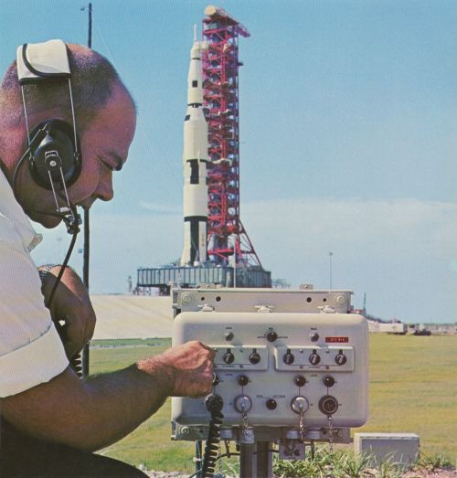
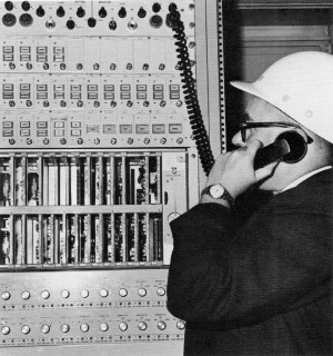 Engineer checks out Collins communication system at Launch Pad 39A. |
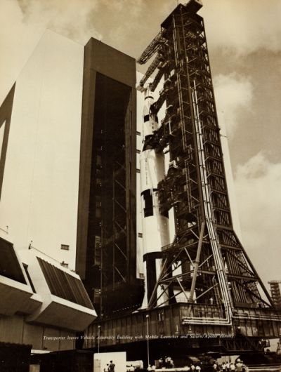 Transporter leaves VAB with Mobile Launcher and Saturn/Apollo Dummy. |
The MSOB contains two altitude chambers, each large enough to accommodate a complete Apollo spacecraft system. Within these chambers, environments equivalent to an altitude of 250,000 feet can be simulated in one hour. Each Apollo spacecraft system will be subjected to three altitude tests, with the third test fully manned by the Apollo crew. Other spacecraft tests will be conducted in the MSOB with automatic equipment, capable of checking some 2500 parameters. Alpha-numeric checkout data will be displayed in checkout control rooms and at remote areas on ten inch cathode ray tubes. Apollo astronauts will live in MSOB crew quarters for 90 days preceding their flight. During this period, the astronauts will accompany their spacecraft as it undergoes its final testing phases. Five miles north of the industrial area sprawls LC-39. Its major components:• Vehicle Assembly Building (VAB) • Launch Control Center (LCC) • Three Mobile Launchers • Two Transporters • Crawlerway • Mobile Service Structure • Two Launch Sites, 39A and 39B LC-39 represents a break with the traditional method of readying and launching spacecraft. This traditional method involves 1 ) assembling the space vehicle on the pad from which it is to be launched 2) connecting checkout and ground support systems, and 3) launching the vehicle from a nearby blockhouse. In contrast to the rigidity of the traditional method, LC-39 embodies a mobile concept. The Apollo/Saturn will be assembled and checked out on the mobile launcher in the controlled environment of the VAB, then transported with the launcher to a pad. Besides enabling NASA to maintain the integrity of test connections, the mobile concept will provide a higher launch rate, more economic operations and greater flexibility. These factors will insure that the Space Center can accommodate the hardware involved in America's space program for decades to come. |
|
Towering 52 stories above and covering 8 acres of Merritt Island, the VAB is the world's largest building. Through one of its mammoth entrances, a 46-story building could pass with ease. Enclosing 129 million cubic feet, the windowless VAB rests on 4225 steel pilings, driven 160 feet down to bedrock. Ninety-four thousand tons of steel went into the VAB, which includes two major work areas: a 525-foot tall high-bay area and a 210-foot-tall lowbay area. The high-bay area contains four vehicle assembly and checkout bays, each capable of accommodating a fully assembled, heavy-class space vehicle. The low-bay area contains eight preparation and checkout cells for the upper stages of the Saturn V vehicle. The first stage, S-lC, will be towed to the high-bay area and erected on a Mobile Launcher. Four holddown support arms on the Mobile Launcher platform will secure the booster in place. Work platforms will be positioned around the booster for inspection and testing. Concurrently, upper stages of the Saturn V will be delivered to the low-bay cells, inspected, and tested. When testing of the individual stages is completed, the upper stages will be prepared for mating and moved to the high-bay area. All components of the space vehicle, including the Apollo spacecraft, will be assembled vertically in the high-bay area. The fully assembled space vehicle then will undergo final integrated checkout and simulated flight tests. Connected to the high-bay of the VAB by an enclosed bridge is the LCC, combination administration area and blockhouse of LC-39. On the first floor of the LCC are offices, dispensary, and a cafeteria. The second floor is allocated to telemetry, measuring, and checkout systems for use during stage and vehicle assembly and for launch operations at the launch site. Four firing rooms occupy the third floor - one for each high bay in the VAB. These rooms will contain control, monitoring, and display equipment required for automatic vehicle checkout and launch. Each firing room will be supported by a computer room, key element in the automatic checkout and launch sequence that will be employed for Apollo/Saturn. |
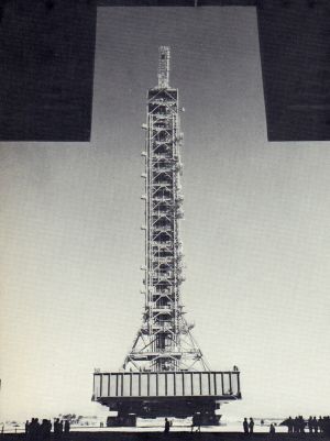 Mobile Launcher on Transporter framed by VAB doorway. |
|
Direct viewing of the firing rooms and the launch area is possible from the building's mezzanine level through specially designed laminated and tinted glass windows. Mobile Launchers actually perform a dual function. They serve as assembly platforms within the VAB and as launch platforms and umbilical towers at the launch pads. Each Mobile Launcher is a 446-foot-high structure with a base platform measuring 24 feet high, 160 feet long, and 135 feet wide. The launchers weigh 10.6 million pounds apiece. Whether in the VAB, at the launch site, or in its parking area, each Mobile Launcher is positioned on six 22-foot-high steel pedestals. The Apollo/Saturn V will be positioned on the Mobile Launcher and secured by four support and holddown arms. At the pad these arms will hold the vehicle during thrust buildup of the engines. |
|
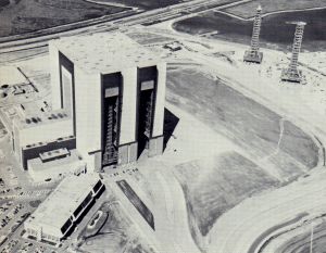 Aerial view of VAB, LCC and Mobile Launchers. |
The herculean task of moving multi-million-pound loads about LC-39 is performed by the Transporters. Resembling those iron behemoths used for strip mining, each Transporter weighs 5.5 million pounds. They have platforms 131 feet long, 114 feet wide and some 25 feet above the ground. Hydraulic leveling systems maintain the level of payloads to within ±10 minutes of arc. The Transporters move on eight treads, driven by 16 traction motors. These motors are powered by four 1,000-KW generators, turned by two 2,750-hp diesel engines. Two other diesels generate 2,130 hp for leveling, jacking, steering, lighting, ventilation and electrical systems. A Transporter has a top speed of 1 mph loaded and 2 mph unloaded. In operation, a Transporter will crawl under a Mobile Launcher and space vehicle inside the VAB. The Transporter's 16 hydraulic jacks will raise the Mobile Launcher, with the space vehicle aboard, from support pedestals. Then the Transporter will back out of the VAB and transfer the 11.5-million-pound load some 4 miles to the launch site. The combined weight of a Transporter, Mobile Launcher and Apollo/ Saturn V will exceed 17 million pounds. To accommodate this load, the Crawlerway extends from the VAB to the launch site. Consisting of two 40-foot-wide lanes separated by a 50-foot-wide median strip, the Crawlerway has a roadbed 7 feet thick. |
|
The Mobile Service Structure is a 402-foot-high tower that weighs 12 million pounds. It contains five service platforms to provide 360-degree access to the space vehicle for final servicing at the launch site. The two lower platforms can be adjusted up and down the vehicle, while the three upper platforms have a fixed elevation. The Apollo astronauts will gain access to the spacecraft from one of the upper platforms. Like the Mobile Launchers, the Mobile Service Structure will be carried to a launch site by a Transporter. The Mobile Service Structure will be removed from the pad a few hours prior to launch and returned to its parking area. The two launch pads at LC-39 are approximately four miles from the VAB. Each pad is an eight-sided polygon measuring 3,000 feet across. The major elements of the launch pads include storage tanks for liquid oxygen, liquid hydrogen, and RP-1 propellants; gas compressor facilities, and associated umbilical connection lines necessary for launching the space vehicle. The top of each pad is equipped with steel support pedestals for positioning a Mobile Launcher and the Mobile Servicing Structure. |
|
 The RADIC System - Cover, Fall 1966 issue of Collins Signal. |
Collins is participating in the outfitting of LC-39 through the installation of an RF communication system. It is a phase-locked, closed-loop system utilizing single-sideband, suppressed-carrier and frequency-division multiplex techniques for voice communication. The Collins system was chosen over conventional hard-wire systems because of its high channel capacity, minimum amount of wiring, superior voice quality, and flexibility. At LC-39 the Collins system is designated by NASA as the Operational Intercommunications System (OIS). Collins is providing the OIS under contract to the U.S. Army Corps of Engineers/Canaveral District, executive construction agent for the Space Center. Collins' first installation at the Space Center was in the MSOB. Equipment there includes a system center amplifier, 60 telephone line interface modems, and five branch cable pairs containing approximately 200 dual-operator stations. Since the initial MSOB contract, Collins has built and delivered approximately 2000 dual-operator stations, 60 special purpose stations, Local Communication Area, mission control and interface equipment for LC-39. OIS system center equipment is installed in the Communications Control Room (CCR) in the LCC. Pairs of transmit and receive coaxial cables extend from the CCR to all areas of the launch complex. The LC-39 cable plant resembles a giant wheel, with the CCR system center equipment at the hub and radial branch pairs as spokes. One of the LCC firing room branches represents a typical branch cable installation. Two RG-213 coaxial cables extend from the CCR to the firing room, and each is terminated in 50 ohms at the far end. Dual-operator stations are attached to the transmit and receive cables and to two power cables through a passive line tap. |
|
Line tap probes pierce the coaxial cables, connecting to both the center conductor and shield. Similar probes pierce the power cable insulation to contact the conductors. All connections are made simultaneously when the line tap is tightened onto the cables. Thus, there is no service disruption when stations are added or removed from the lines. Both single line taps, for one dual-operator station, and multiple line taps, for up to five dual-operator stations, are utilized at LC-39. Either line tap is installed in the same manner with no system operational disruption. A pair of branch cables may be loaded with as many as 100 dual-operator stations without decreasing the input RF signal to a station more than 3.5 db. on each leg. Many areas at LC-39 require extensive communication capability. Such an area will be a pad, where camera sites around the perimeter, a Mobile Launcher, the Mobile Service Structure, and various other areas must be combined into a communication network and connected to an LCC firing room. Rather than extend all these coax pairs back to the LCC-CCR system center, a small system center at the pad combines the various communication branches and routes them to the LCC-CCR on one pair of cables. Small system centers, known as Local Communication Areas (LCA), are located at both pads and at six other LC-39 facilities. All branch and LCA trunk cables enter the CCR center through RF patch panels. Two mission amplifiers, each capable of accepting up to 64 branch and trunk cables, are presently installed in the CCR. A typical launch mission may require that the vehicle unload area, instrumentation facility, high pressure gas converter, VAB low bay, VAB high bay, firing room, Mobile Launcher, and a pad be connected. This is accomplished in the CCR by RF patching all these areas into one mission amplifier. Patched in this manner, any dual-operator station at any of the locations may communicate with any other station on one of 112 channels. If it were desired, all operators could select the same channel with their front panel selectors and communicate with one another on the same channel. Mission amplifier capacity is great enough so that all OIS areas in LC-39 could be patched together. The CCR center equipment also contains interface circuits to systems outside the OIS. Modems are provided for the OIS interface for two-wire or four-wire audio lines. A mission may require that NASA facilities at Huntsville and Houston be connected to the OIS. By extending telephone lines to the modem interface, the remote facility can be connected to any or all OIS stations. Modem connection is such that no sidetone is transmitted back onto the audio line; this follows standard practices for the telephone systems. All LC-39 dual-operator stations are equipped with a front panel page switch, which connects the talkers through CCR mission center interface equipment to an LC-39 paging bus. This allows wide paging from any OIS station. OIS communication to the Transporters are by UHF links. All Mobile Launchers and the Mobile Service Structure communicate through the Transporter UHF link when in transit. These systems communicate via cable when at the pad, the VAB, or their respective park areas. |
|
|
For OlS branch and trunk coaxial cables longer than 600 feet, compensation is made for cable frequency roll-off and wide-band cable loss. The LC-39 cable plant is equalized through 3 MC, even though the highest frequency in the existing 112-channel equipment is 500 KC. Equalization through 3 MC for a 600-channel system is provided in the OIS cable plant since all LC-39 OIS equipment is designed so that channel capacity can be increased by merely changing or adding circuit cards. OIS equalizers are fixed and passive. Collins utilizes a computer program to determine equalizer component values. These equalizers are used in conjunction with wide-band amplifiers to provide a flat frequency response over the operating frequency spectrum. All CCR system center equipment, including cable equalizers, and all LCA center equipment at LC-39 are equipped with fault sensing circuitry and automatic switchover to redundant back-up circuits. The sensing of a fault not only initiates circuit switchover but also activates visual and aural alarms. Faults at the remotely located LCA centers are indicated both at the LCA equipment and at the LCC-CCR. OIS fault alarms may be extended further if a system monitor at some other location is desired. Dual-operator stations are essentially two single-sideband transceivers housed in one case. A 4-KC pilot tone originating in the CCR system center serves as a reference signal for frequency synthesizer phase lock in all OIS operator stations. Each station generates its 500-KC IF by amplifying the 125th harmonic of the 4-KC reference. Balanced modulators and Collins mechanical filters are used for single-sideband suppresed-carrier signal generation. Frequency synthesizer frequencies are selected in 4-KC increments, thus establishing a 4 KC channel bandwidth. |
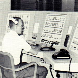 All OIS communication lines lead to this system in the LCC. |
|
In the l12 channel system, the phase-locked synthesizer provides frequencies from 516-960 KC in 4-KC steps, controlled by the station front panel channel selector switches. The lower sideband of the second modulator is selected, resulting in transmitted frequencies of 13-15.7 KC for the lowest channel. Operator stations are equipped with a VOX circuit in the transmitter section. The receiver section, which uses the same modulation frequencies as the transmitter, is equipped with a squelch circuit and 15 db of AGC. OIS stations can function in two modes: dual and active/monitor. In the dual mode, each side has 112 identical channels; the station functions as two independent transceivers. In the active/monitor mode, both operators at a station transmit on an active channel and receive simultaneously on both the active and monitor channels. Provided are individual output level controls for both operators. Each side of a dual station is also provided with one headset connector at the rear. Two electrically identical station configurations have been provided for LC-39. One is a 19-inch rack-mounted station for console areas. The other, a quick-disconnect, wall-mounted sealed unit, is for hazardous and outdoor environments. In hazardous areas, the sealed station is pressurized with inert gas. Firing room test conductors have special OIS stations. These stations provide access to any OIS channel, quick access for up to 18 audio lines, standard telephone operation, paging, talk, listen, and conference bus capability for any combination of the 18 quick-access lines. CCR power and the power for all critical OIS areas is provided by float chargers, under normal operating conditions, and by battery banks in the event of ac power failure. Additional OIS system center amplifier equipment for the MSOB is currently under development at Collins. When this equipment is installed, the MSOB will have a much greater communication capability. The new MSOB system center amplifiers can be connected via wide-band transmission lines to the LCC-CCR. With its flexibility and expandability, the OIS is destined to grow with the Space Center as it assumes ever greater responsibility in America's space exploration program. |
|
| —Collins Signal, Issue 61, Volume 14-3, 1966 - Pages 16-21 | |