|
|
|
| MOON TALK VIA S-BAND | |
|
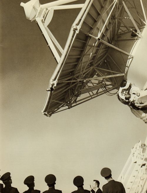
When U.S. astronauts journey to the moon, they will be linked to earth by a pencil-thin radio beam generated by a completely new communication and tracking system. This tiny beam will handle voice and data communication and tracking. Far simpler and more reliable than the systems currently in use, the new system will play a critical role in the historic lunar mission. During the upcoming Apollo project, many maneuvers are planned that have never been attempted before. One of these will be the simultaneous flight of the mother spacecraft (Command Module) and offspring (Lunar Excursion Module) near the moon. Handling the demanding new requirements of these unprecedented activities will be the Unified S-Band tracking/communication system. It is labeled unified because tracking and communication will be accomplished by one system using a single band of radio frequencies. Now telemetry, voice communication and tracking are being handled with separate stations on different frequencies. The Unified S-Band System will consist of a network of 15 ground stations located strategically about the globe. Twelve of these, each with a 30-foot-diameter antenna, will provide continuous horizon-to-horizon coverage while the spacecraft orbits the earth. These 30-foot stations will be supplemented with range tracking ships and aircraft. Three stations with 85-foot-diameter antennas will be spaced approximately equidistant around the world. They will support the mission when the Command Module (CM) and Lunar Excursion Module (LEM) are in deep space beyond the range of the 30-foot stations. To illustrate the need for different size stations, imagine the earth as seven feet in diameter. A spacecraft orbiting this size earth would be about one inch above the surface. It's easy to see how the horizon would frequently cut into line-of-sight communication and tracking unless several stations were spaced around the globe to continually illuminate the orbiting spacecraft. However, when the spacecraft probes deeper into space toward the moon, the horizon presents less of a difficulty. Then fewer but more powerful stations will be required because of the tremendous distance involved. In scale with the seven-foot earth, the 20-inch moon would be about 200 feet away. |
 |
|
Design, construction and installation of the ground stations is being performed by Collins Radio Company under a $25 million-plus contract from NASA's Goddard Space Flight Center (GSFC). In addition, Collins is providing partial systems for Apollo range tracking ships and three Jet Propulsion Laboratory stations that will serve as back-ups to the primary GSFC 85-foot stations. Stations using 85-foot antennas will be at Goldstone, California; Madrid, Spain, and Canberra, Australia. Thirty foot sites are Ascension Island; Antigua Island; Bermuda; Canary Islands; Goddard Space Flight Center; Cape Kennedy; Texas; Guaymas, Mexico; Hawaii; Guam; Grand Bahama Islands, and Carnarvon, Australia. Some 30-foot stations and all 85-foot facilities will be able to communicate simultaneously with both the CM and LEM. This is most important when the LEM is landing on and taking off from the moon. |
|
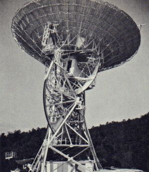 An 85-foot-diameter antenna. |
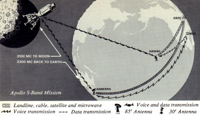
Simultaneously The Unified S-Band System will allow voice, data and a ranging (distance measuring) sequence to be transmitted simultaneously from an earth station to the spacecraft. Similarly, information from the spacecraft to ground may be combinations of telemetry, voice, slow-scan television, and the ranging sequence. The ranging sequence will be transmitted to the spacecraft and immediately retransmitted back to earth automatically. The time necessary for the round trip will be used to compute the distance between the two. A change in the frequency of the returning signal (doppler shift) will be used to determine spacecraft speed.Communication and data equipment on the spacecraft will also be provided by Collins. Among this equipment will be S-band transceivers, VHF transceivers, intercommunication and associated equipment. Certain essential equipment will have identical back-up units. The CM and LEM can communicate with each other via the low power VHF radios. Frequencies to be used are approximately 2100 mc from earth to CM (up-link) and 2300 mc from CM to earth (down-link). Both phase modulation and frequency modulation techniques will be employed. Each station will be connected with the Manned Spacecraft Center (MSC) in Houston, which will control the missions, and with Goddard Space Flight Center in Greenbelt, Maryland. Voice transmission to and from the spacecraft can be forwarded instantly through the S-Band stations. Some data will be used to update information at the ground stations. Other data will be relayed from the stations to MSC and GSFC. |
|
High-gain parabolic antennas will be used at the stations to enhance tracking accuracy and communications sensitivity. The 30-foot antenna beam is slightly less than one degree wide - an extremely narrow beam that re-quires high precision in the servo control that moves the antenna. Beam width of the 85-foot antenna system is one-third as wide as the 30-foot antenna beam. Three methods can be employed by stations to point the antenna accurately at the spacecraft: A complete Unified S-Band facility will include an instrumentation building, an antenna system and a collimation site. The electronic equipment at such a facility includes data equipment, communication/tracking receiver, ranging subsystem, optical collimation subsystem, RF collimation subsystem, transmitter, and the servo control console. The instrumentation building will contain an operations room, test labs and an office area. Used only for testing, the collimation system will not be directly involved in communication with the spacecraft. This system includes a tower located a short distance from the station, two 4-foot antennas, a boresight transmitter, a remotely controlled attenuator and two GFE test transponders. The collimation system will be used to simulate communication with the spacecraft, allowing a station to check out virtually all systems in advance of need. |
|
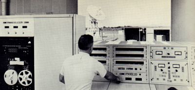 An engineer checks out the 30-foot antenna (visible through window) from control console. Part of the S-Band digital data equipment is shown on the left. The antenna ball tracker is at right. |
RF Subsystem The RF subsystem will be used to amplify and transmit the signal to the spacecraft and to receive and amplify the incoming signal before feeding it into other station equipment. This subsystem consists of the antenna feed assembly, power amplifier, receiver system, parametric amplifiers, verification receiver, collimation system and acquisition antenna. Forty inches in diameter, the acquisition antennas will be mounted at the apex of the large antennas. With a beamwidth ten times that of the 30-foot antenna (and a corresponding reduction in gain), the acquisition antenna will be used to help locate and track the spacecraft. |
|
The digital data subsystem includes the timing subsystem, the antenna position programmer, the tracking data processor and the antenna shaft positioner encoding system. The timing subsystem provides time information in several forms for use by other station operations. Parallel binary and binary-coded-decimal time-of-year forms are included with various time codes and timing pulse signals. The system has two time standards, a status clock and a signal distribution subsystem. Steering Signals The antenna position programmer (APP) will provide antenna steering signals to operate the servo system that moves the antenna. The APP has two fundamental modes of operation: "auto" and "program." In the "auto" mode, the antenna will automatically track the spacecraft with signals received from it. While this is going on, the APP will continuously compare the antenna position with what the command (predicted) information says the position should be. If any discrepancy is present, it will be stored in the computer memory for possible later use. Tn the "program" mode, the APP points the antenna where previously programmed information says the spacecraft should be. This mode will be used when initially trying to pick up the spacecraft or in case actual tracking contact is lost or degraded. The antenna shaft position encoding system "reads" the position of the antenna's X and Y shafts 10 times a second and feeds the information back into the APP. Accuracy of the encoding system is 15 seconds of arc peak. The tracking data processor (TOP) will assemble tracking data, range and range rate data and other station operation data and transmit it to GSFC. Some preprocessing will take place before transmission to Goddard via high-speed modem (modulator-demodulator) or low-speed teletype communication links. The analog data system is composed of the updata subcarrier oscillator, the signal data demodulator and the updata buffer. The updata subcarrier oscillator will accept all information to go to the spacecraft, modulate the different inputs and combine them into the single signal before routing it to the RF subsystem for transmission. Removal of information from the received spacecraft composite signal is the purpose of the signal data demodulator. A number of modulations are involved, such as TV, voice, telemetry and mixed FM-FM subcarrier for biomedical data. After separation from the main S-Band carrier, the various signals will be transmitted to displays and recorders in the station and/or in the NASA communications network. |
|
|
Updata Buffer The updata buffer subsystem will change the command data from the GFE computer (sent in parallel binary form) into a serial binary bit stream and then convert it to biphase modulation. The biphase modulation, together with a clock tone, will then be transmitted to the spacecraft. In addition, the updata buffer will accept a signal from the verification receiver and reconvert it for entry into the GFE computer, where the signal will be checked for accuracy against the original command. The first of the 30-foot S-Band stations is now being installed on Guam. All of the stations are scheduled for completion in 1967. |
 |
| —Collins Signal, Issue 58, Volume 13-3, 1965 - Pages 6-9 | |