Getting Quality Performance With Class B Modulation Practical Design and Operating Data for Best Tube Combinations
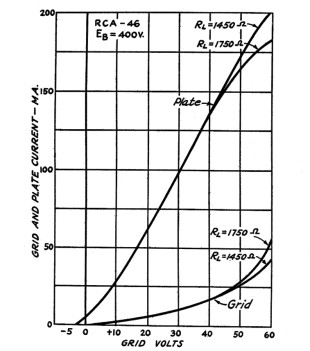
By Arthur A. Collins, W9CXX*
CLASS B modulation met with instant approval in amateur circles.
Since it was first presented in QST1 some two years ago, thousands of amateur 'phones have changed over to Class B because its economy and the possibility of getting a lot of power out of little tubes appeal forcibly to the amateur.
With Class B operation you can get five to ten tinnies the audio power output possible with Class A operation of the same tubes, and this greater output can be obtained with negligible distortion.
But what is “negligible distortion”? The very cheapness of the system has led many conservatives to lift their eyebrows; “Perhaps it’s all right for voice but not for music.”
Some light appeared to be thrown on the subject by certain published charts which plotted percent total harmonics against power output.
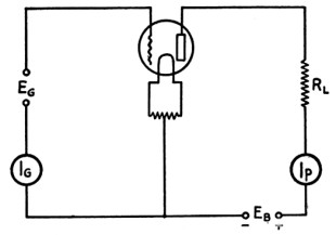
FIG. 1-CIRCUIT USED IN DETERMINING THE CHARACTERISTICS OF CLASS B OPERATION
But these charts apparently held for a single set of tubes, drivers and transformers.
Slight circuit changes made big differences in results. The “voice-music” platitude apparently was going to be settled by the introduction of commercial models of broadcast receivers with Class B in the output stage.
Certainly set engineers would not employ Class B if it was not OK.
Listening to these new b.c. receivers usually leaves an uncertain impression as to fidelity.
Some of the best makes sound pretty good but others, especially the cheaper ones sound “hazy,” “fuzzy” or “rattley” to the critical ear.
Neither does listening to Class B amateur 'phones lead to conclusive results.
* Collins Radio Company, Cedar Rapids, Iowa. 1 Barton, “The Class B Push-Pull Modulator,” Nov., 1931; Lamb and Grammer, “High-Power Performance From The Small 'Phone Transmitter,” Dec. 1931, QST.
Some of them sound very good, others sound terrible. And then the offhand judgment of the human ear isn’t very reliable anyway.
In this article I shall attempt to set down the results of development work extending over a considerable period of time and having to do with Class B amplification and Class B modulation.
In this work the possibilities and limitations of this system have been quite carefully studied, and the different kinds of distortion peculiar to Class B have been analyzed and means found for overcoming them.
Lest the word “distortion,” used repeatedly in the following paragraphs, make the situation sound a little hopeless, it might be well to state at this point that it has been proved that Class B modulation is extremely well suited for use in high quality radiophone installations when the operating and circuit conditions are what they should be.
The general relations governing Class B circuits are well known, but are repeated briefly here for reference.
The performance of any tube under ideal conditions can be studied by plotting its grid and plate current for different values of grid voltage and plate load (circuit of Fig. 1).
The following equations hold:
Since the grid swings positive, it will draw current and consume power.
The grid power is represented by the area under the grid curve.
The grid impedance of most tubes is not linear and therefore the grids must be driven from a source having good regulation.
This fact has been mentioned repeatedly, but many amplifier designers seem to have overlooked the strict requirements imposed by the grid circuit.
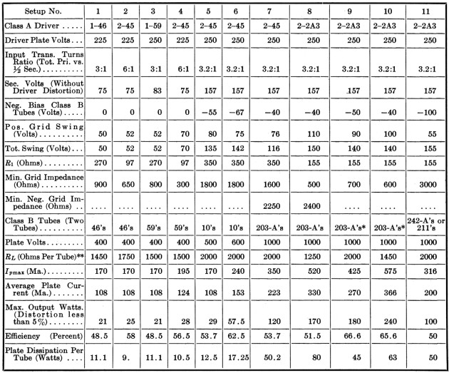
To illustrate this point let us look at Fig. 2, the load curves for the familiar 46 tube.
DRIVER REQUIREMENTS
The grid curve is approximately a straight line out to about Eg= +40v. and its slope corresponds to an impedance of about 4000 ohms.
However, the grid current increases rapidly as the grid swings past 40 volts, the exact slope of the curve depending on the plate load.
QST - May, 1933
15
The value of grid impedance at any point can be calculated by drawing a tangent to the curve at that point and measuring the slope.
When the grid swings to +50 volts, the grid-impedance has dropped to about 900 ohms (RL= 1450 ohms).
Now it is evident that the input voltage will be seriously distorted by the grid load varying between 4000 ohms and 900 ohmsunless precautions are taken so that the driver has very good regulation.
Good regulation of the grid voltage can be obtained by using a power type Class A driver tube (or tubes) having low plate, impedance, and by using an input transformer having as large a step-down ratio as is consistent with getting the required grid swing.
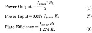
Table I gives operating data on eleven different tube setups for Class B modulation.
Let us analyze the driver requirements of Setup No. 1, a single 46 Class A driving two 46’s Class B.
The Class A 46 has a plate impedance of 2400 ohms.
It is coupled to the two Class B grids by a transformer with a turns ratio, total primary to ½ secondary, of 3 to 1.
The peak voltage which can be developed across one-half the secondary is approximately equal to the driver plate volts divided by the turns ratio of the transformer.
In this case 75 volts could be obtained whereas only 50 volts peak are required — a comfortable margin.
Now the impedance across the primary of the transformer can be referred to the secondary by dividing it by the square of the turns ratio;
2400/32 = 267 ohms, which can be considered as a resistance in series with a generator with perfect regulation.
This series input resistance is referred to as R1 in the table and in Fig. 3.
R1 should be small with respect to the minimum grid impedance if distortion of the grid voltage is to be avoided - about ⅓ to ⅙ the value of the latter, depending on the exact shape of the grid curve.
Having found that we are driving the Class B tubes satisfactorily, let us read on across the line and see what we are getting out of the setup.
Fig. 2 shows that a peak grid voltage of +50v. gives.a peak plate current (Ip max) of 170 ma. through a load resistance (RL) of 1450 ohms.
The average plate current to the two tubes, as read on the plate milliammeter, is 170 X .637 = 108 ma.
Equations (1) and (2) give the output as 21 watts, the efficiency as 48.5 percent and the plate dissipation per tube as 11.1 watts.
Experience has shown that calculated and observed outputs agree very closely when efficient transformers and power supplies of good regulation are used.
The illustration just given shows that Caleb B performance can be predicted quite easily - until you run into the “bugs.”
But before we consider the “bugs” and how to eliminate them, let us look down the list a little further and see what can be accomplished with different tube arrangements.
Setup No. 2 is justified by lower ratio series resistance to grid impedance (over 6 to 1), greater output (25 watts), greater efficiency, and even less distortion, as compared to Setup No. 1.
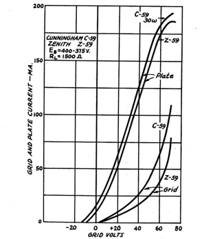
The next line and Fig. 3 show the performance of 59’s driven by a single 59 Class A under most favorable conditions.
There is little to choose between the 59’s and 46’s in the same arrangement.
Table I
* Newest Type (Carbon Plate) *** Multiple by 4 to get plate-to-plate impedance for 2 tubes.
16
QST - May, 1933
But the output from 59’s can be boosted to 28 watts by swinging their grids to +70 volts with push-pull 45’s. (Setup No. 4).
Fig. 3 shows that excessive grid currents are drawn past Eg= 70 volts, and it is not practicable to attempt much higher output from these tubes.
FIG. 3-CLASS B CHARACTERISTICS OF TWO TYPES OF 46’S
In fact, the driving power required with multiple-grid zero-bias tubes becomes so large at about this point that it may not be advisable to design larger tubes of this type.
The next step in the direction of more power is the familiar 10, which was one of the first tubes suggested for Class B work.
Setup No. 5 is the customary 10 arrangement with a plate voltage of 500, delivering 29 watts output. (Note that a 3.2:1 input transformer is used instead of the usual 2:1.
Result: Vast improvement in quality.) Note also that 59’s driven by 45’s will deliver almost as much power, though they are cheaper tubes and require a less expensive power supply.
But by raising the plate voltage on the 1O’s to 600 volts (Setup No. 6) we can really get performance!
Output is 57.5 watts with an efficiency of 62.5 percent.
There is no increase in distortion if an adequate output transformer is used.
Each tube dissipates 17.25 watts from its plate — which is 2.25 watts above rated value.
However, this occurs only on loud passages and the average plate temperature will remain below normal.
This is an excellent example of the way Class B output can be increased by raising the plate voltage so that allowable plate dissipation becomes the limiting factor rather than filament emission.
This expedient should not be tried on 46’s and 59’s because their complicated structure won’t stand the voltage.
Plate load resistance usually should be increased with plate voltage and the whole idea must be handled with gloves in the absence of exact measuring equipment.
Setups 7 and 8 of Table I show the performance of 203-A’s with p.p. 45’s and p.p. 2A3’s as drivers.
The outputs shown are about the maximum obtainable from the type of 203-A’s (or 503-A’s) generally in use at the present time.
Setups 9 and 10 indicate the marked improvement made in the very latest style of 203-A which is identifiable by its “carbon” (black) plate.
The outputs are greater, efficiency is higher and the grids are easier to drive.
These new tubes are also relatively free from secondary emission.
Setup 11 shows that 211’s (or W.E. 242-A’s) in Class B are good for 100 watts output but have the disadvantage of high bias requirements.
However, the grid impedance is high so that they are easy to drive.
FIG. 3-CLASS B CHARACTERISTICS OF TWO TYPES OF 59’S
Type 845’s are ruled out because of their large secondary emission from the grid.
QST - May, 1933
17
As a rule, the medium- or high-mu tubes are more convenient to handle.
TRANSIENT DISTORTION
Now for the “bugs” and “parasites.”
It is necessary to use transformers to couple the Class B tubes, to work in the familiar “push-pull” Class B circuit, and no transformer functions perfectly in its role of transferring a resistive load from primary to secondary.
The leakage reactance and distributed capacity present in all transformers introduce certain complications in the circuit of Fig. 1, which must be taken into consideration in studying the performance of a Class B circuit.
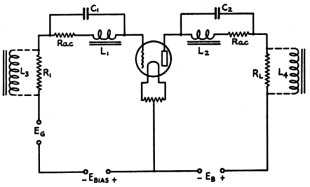
The equivalent network for a single Class B tube with transformer coupling to input and output circuits is shown in Fig. 4.
Refer first to the grid circuit.
R1 is the input resistance introduced by reason of the plate impedance of the driver stage.
L1 is the leakage reactance of the input transformer and C1 is its distributed capacity. Rac represents the a.c. resistance of this circuit.
In a similar way a resonant circuit appears in the plate circuit by virtue of the leakage reactance L2, distributed capacity C2 and a.c. resistance Rac of the output transformer.
Of course the input and output transformers each have a mutual inductance represented by L3 and L4, respectively.
This circuit bears some similarity to the familiar tuned-plate tuned-grid transmitter circuit and one might expect oscillations or other disturbances to be set up which would not be present in the basic circuit of Fig. 1.
There is not sufficient coupling at audio frequencies through the tube capacities to cause oscillations in the ordinary fashion, but very distressing things can happen just the same.
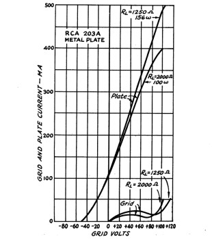
Fig. 5 shows the plate and grid curves for a 203-A tube of the older type.
It will be noticed that, although the plate curve is straight over the greater part of its length, the grid curve represents a non-linear impedance and at one point the resistance is actually negative, as represented by a downward slope.
The fact that the input resistance of the tube is not linear makes it necessary to employ a driver circuit having very good regulation.
But this is not the entire difficulty.
A circuit which has negative resistance is prone to oscillate in a “dynatronic” fashion.
Thus the tank circuit which exists by reason of the leakage inductance and distributed capacity in each half of the input transformer secondary will tend to oscillate at its natural period when the grid swings through the portion of the curve where it has negative resistance.
FIG. 4-THE EQUIVALENT CIRCUIT OF A CLASS B STAGE WITH TRANSFORMER COUPLING
Oscillation will actually occur when the negative resistance is equal to, or less than, the shunt impedance of the tank.circuit L1 C1 R1. The values of L1 and C1 which are likely to occur in practice will give a resonant circuit having a fundamental frequency of from 4000 to 20,000 cycles.
Thus these oscillations may occur within the upper range of audibility.
When this condition exists the oscillations can be very easily detected if the output of the Class B amplifier is connected to a cathode ray oscillograph.
Over certain portions of the signal wave there will be small envelopes of high frequency oscillations which look very much like a drawing of a modulated radio frequency carrier.
These transient oscillations do not persist over an appreciable part of the cycle because of the high damping which is usually present and because the grid exhibits negative resistance only during a short time in its positive swing.
Grid transients of this character are found only with certain tubes, including the 30, 112-A, 203-A and 849.
The newer high-mu tubes, such as the 46’s, 59’s and 79’s, which have been designed especially for Class B use, do not have a negative grid resistance at any point and they are relatively free from this difficulty.
18
QST - May, 1933
Transients occurring in the grid circuit.have been observed on the cathode ray oscillograph with an amplitude almost as great as that of the signal frequency, and of course this is a very serious condition.
A Class B amplifier operating under this handicap will sound “fuzzy” or “indistinct.”
Since all transformers, no matter how carefully built, have a. certain small value of leakage inductance and distributed capacity, it might appear to be quite difficult to eliminate the grid tank circuit which gives rise to these oscillations.
However, the problem is not hopeless, and, in fact, the difficulty can be very easily corrected.
FIG. 5-THE GRID CHARACTERISTIC OF THE OLDER TYPE 203-A’S SHOWS NEGATIVE RESISTANCE
When tubes which have a “kink” in their grid characteristic are used, all that is necessary is to place a resistor between grid and filament which has a value approximately equal to the negative resistance of the grid circuit.
A convenient value which serves for 203-A’s, 211’s, 204-A’s and 849’s is 5000 ohms.
This resistance is considerably higher than the input series resistance R1 and causes very little additional loading on the driver stage.
Transients can also occur in the plate circuit of the tube independently of grid circuit transients.
Plate transients will have a frequency in the upper audible or super-audible regions, determined by the Leakage reactant and distributed capacity of the output transformer (L2 C2).
Oscillations in this tank circuit may be excited over certain portions of the cycle by virtue of the fact that the plate current in each tube is not sinusoidal, but is approximately a half sine wave with slight irregularities caused by curvature both at the upper and lower ends of the plate characteristic.
The plate impedance is, of course, never negative but oscillation can be started in an LCR circuit by switching on and off an a.c. wave.
The ratio of oscillation amplitude to the signal amplitude depends upon the point at which the current flow is started and stopped.
Transients of this kind can be analyzed mathematically.
Plate transients are usually less severe than grid transients unless an output transformer is used which has a high leakage inductance.
Plate transients, of course, could be damped out in the same way as grid transients by connecting a resistor between the plate and “B”-plus.
The amount of power lost in this resistor can be reduced by connecting a small capacity in series with it.
If this expedient is necessary, serious attenuation of the high audio frequencies can be avoided by using a fairly large value of resistance and a small capacity which, nevertheless, will have a low reactance to the high-frequency transients.
(A similar capacity-resistance load is sometimes placed between the plates of two Class B tubes, not only to avoid plate transients, but also to correct the frequency response of some types of loud speakers.)
In general it may be said that high-frequency transients can be one of the most serious causes of distortion in Class B systems.
Their presence is sometimes overlooked because they will'not show on a string oscillograph.
They can be eliminated entirely, however, by the simple expedients outlined above.
INPUT TRANSFORMER DISTORTION
As explained before, the input transformer must have exactly the correct turns ratio.
Many input transformers on the market have a lower step-down ratio than that indicated in Table I.
A variation of 25 percent in the ratio will often cause an increase of 5 or 10 percent in the harmonics.
But in addition to this. requirement the input transformer must have very close coupling between primary and secondary; it must have low leakage inductance. High leakage inductance will introduce additional series input impedance at high frequencies and will aggravate tendencies toward transients.
An efficient input transformer may employ inter-spaced or “pi” windings.
OUTPUT TRANSFORMER DISTORTION
Harmonic distortion is caused not alone by improper driving of a Class B stage but also by an inadequate output transformer.
One of the most common deficiencies in output transformers is too low primary inductance.
Suppose that the total primary inductance of an ordinary transformer is 12 henries under operating conditions.
Each tube is connected across only half of the primary or across an inductance of 3 henries.
Its reactance is in shunt with the load resistance and is equal to XL = 2πfL.
If a bass note of 80 cycles is sent through the system, XL = 1500 ohms.
QST - May, 1933
19
Without complicating this article by the use of vector quantities, it can be said that the tube at 80 cycles is working into a resistive load (RL) of 1450 ohms shunted by an inductance load of 1500 ohms, with the result that the effective load is about one-half what it should be.
The tube will, therefore, draw saturation plate currents, producing strong harmonics of the 80-cycle note.
The higher frequency notes present at the same time will be distorted and the 80-cycle fundamental will be seriously attenuated.
A Class B system handicapped in this way by a low inductance output transformer will sound “rough” and “grumbly” on bass passages.
Poor bass response may be tolerated in equipment used exclusively for speech, since the lowest frequency common in male voices is about 120 cycles, but a bad output transformer can even garble speech to a certain extent.
A transformer with too little inductance is much more serious in a Class B circuit than in a Class A circuit.
In the latter it will only reduce the low frequency response, while in Class Bit will also add annoying harmonics.
It is impossible to compensate for low note attenuation in a Class B output transformer by accentuating the lows in preceding stages, since this will only increase the objectionable harmonics.
A good output transformer should have a primary inductance of not less than 20 henries, and it may run well over 30 henries if extreme bass response is required.
The leakage inductance must be kept very low if plate transients and phase distortion are to be avoided.
About 80 or 90 milli-henries is an acceptable value of leakage inductance for each half of the primary.
Leakage inductance, voltage ratio and distributed capacity must be the same for each half of the primary.
Table II
* Class C amplifier plate efficiency of 70%.
20
QST - May, 1933
Primary inductance of the output transformer is tied in very closely with the questions of flux density and saturation due to d.c. in the secondary winding.
Many output transformers have relatively small cores and, although the plate current to the modulated Class .C stage may be carried through their secondary winding if fidelity is not important, a modulation choke and coupling condenser must be used if core saturation is to be prevented.
Serious harmonic distortion can be introduced by working the core at high flux density, and it is usually desirable to use a very large core with an air gap even if the secondary is not to carry d.c.
For this reason a Class B output transformer will usually be considerably larger than a power transformer of the same rating.
It is more economical and efficient to design a transformer capable of carrying the required d.c. through the secondary than it is to employ a smaller transformer with a modulation choke.
The net cost of the transformer-choke-condenser arrangement will usually be greater than that of an adequate transformer.
However, if a modulation choke is used it must have an actual inductance of 50 to 70 henries (instead of the customary 15 to 30 henries) if inductive loading of the Class B tubes is to be avoided.
DISTORTION DUE TO IMPROPER LOAD RESISTANCE
An examination of the curves for the various Class B tubes shows that small variations in load resistance cause a considerable shift in grid currents and plate saturation currents.
For this reason it is imperative that the Class B stage be loaded properly.
The modulation impedance of a Class C stage is given by
Common values of modulation impedance are shown in Table II.
It is the function of the output transformer to transfer the impedance occurring across its secondary to the plate of each tube in exactly the proper ratio.
It is absolutely necessary to adjust the plate voltage and plate current of the modulated stage to the correct values to obtain full output from the modulators and to avoid distortion.
The sensitivity of Class B tubes to slight changes in load resistance makes it essential that they be worked into a purely resistive load.
This condition is satisfied in plate modulation systems.
However, magnetic speakers and small dynamic speakers make a very poor load for a Class B stage because of their high reactance, which permits their impedance to shift drastically with frequency.
In this difference in load conditions lies part of the explanation of why Class B is more suitable in the modulator than in the output stage of a receiver.
FREQUENCY RESPONSE
If all the requirements set out thus far regarding transformers, tubes, loading, etc., have been carefully observed, no difficulty will be encountered in obtaining a very flat frequency characteristic.
Low inductance in any of the transformers will, of course, cut the bass response.
High leakage reactance will attenuate the highs.
If transients are present there may be a broad peak at the upper end of the scale.
With reasonable precaution it is possible to keep the characteristic flat within 2 db from 80 to 8000 cycles, and with very high-grade transformers the response will be flat from 30 or 40 cycles up to 12,000 cycles.
Large values of output capacity should be used in the plate power supply filter circuits to transmit the very low frequencies, and, of course, the plate supply should have good regulation.