|
|
|
| VOICE from SPACE | |
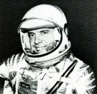 Alan B. Shepard, Jr. |
Washed by the gentle swells of the Atlantic Ocean northeast of Grand Bahama Island, the Mercury capsule “Freedom 7” awaited pick-up by a hovering helicopter. Inside the copter, Navy Commander Alan B. Shepard, Jr., America's first man in space, settled back for the brief airlift to the Aircraft Carrier Lake Champlain. As the 1 ½ ton capsule was hoisted from the sea, green dye, spilled by the recovery dye marker, swirled around the capsule's rubberized skirt. Months of work, study and practice had culminated in America's fastest, highest, manned flight. The entire down range flight - lift off to Atlantic return - occupied just under 16 minutes. At Cape Canaveral a trailer-like van carried Shepard to Launch Complex 5 where the 69-foot Redstone missile stood poised like a giant bullet, blunted on top by the capsule which resembled a huge inverted television tube. Atop the capsule was the derrick-like superstructure of the escape system. |
|
Before the first trace of dawn, Shepard entered the gantry elevator for the first part of his 115 mile climb. Reclining upon a contour couch inside the capsule, he sweated out a 120 minute countdown and still another 120 minute delay because of bad weather and minor mechanical troubles. Finally, at 9:34 a.m. E.S.T. with the morning sun breaking out of clouds to etch sharp shadows into the concrete base of Launch Complex 5, the steel service tower rolled away on railroad tracks and the zero hour arrived. The Redstone flashed life, showering the pad with flaming liquid fuel, and lumbered slowly away from the earth. During the 148 seconds of powered flight, Shepard endured an accelerative force six times his weight as the missile blasted him 115 miles high. At an altitude of 35 miles, the Redstone burned out and the escape tower jettisoned. Ten seconds after burn-out the small rockets at the base of the capsule fired to push the craft ahead and away from its booster. Five seconds later an automatic stabilization and control system flipped the space chariot around 180 degrees so the blunt heat-shielded base was in a forward position. Sitting upright, his back toward the direction he was traveling, Shepard raced along a weightless trajectory through space at a speed of 5,000 miles an hour. Then, in five minutes it was over. The capsule plunged back into the thick atmosphere of space and G forces again gripped the man with nearly twice the strength as before. Temperatures up to 600 degrees Fahrenheit built up on the conical section of the capsule as it dived earthward, but inside his double-walled hull, insulated, airtight and watertight, Shepard noted instrument recordings of less than 100 degrees Fahrenheit, easily tolerated in his air-conditioned spacesuit. At 21,000 feet a small parachute popped out to stabilize the spacecraft. At 10,000 feet a 63-foot main chute blossomed and eased the spacecraft into the ocean 302 miles from its launching point. As the brilliant red and white chute was jettisoned in the ocean wind, special rescue transmitters operated to permit aircraft and surface ships to “home in” with their direction finders to locate the capsule. This link to the recovery force, like the astronaut's link with earth, was provided by a highly miniaturized and rugged electronic communication system, designed and produced by Collins Radio Company in cooperation with a team of eight subcontractors of end-item equipments. |
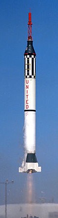 Launch of MR3 |
|
Communication in terms of human language and electrical language was vital to the success of the National Aeronautics and Space Administration's Project Mercury. The journey of the manned capsule involved several phases of flight - prelaunch, launch, flight, re-entry, and recovery and the communications system was developed to cover the requirements of all phases both functionally and environmentally. Supplied by Collins under contract to McDonnell Aircraft Corporation of St. Louis, designers and builders of the Mercury capsule, the Mercury capsule communication system consisted of 30 components produced during two years of developmental work by Collins and its team of subcontractors. Areas of research included: the functional circuits necessary for the several phases of communication; the general problem of signal propagation; several special problem areas in manned-capsule electronics, and each piece of major equipment needed to serve the functions of the capsule system. Mercury Communication Functions Voice Communication. It was necessary for the astronaut and ground personnel to talk to each other during all phases of the mission. Redundant equipment was used to give reliable voice communication in both flight and rescue operations. Command Function. Redundant command receivers with a substantial number of on-and-off channels were provided to control various functions within the capsule during the launch, flight and re-entry. Telemetry. Two telemetry transmitters were provided to transmit scientific, operational and aeromedical data from capsule to ground. Precision Tracking. Two radar transponder beacons in the microwave frequency range were used for precision tracking during flight. Rescue Beacons. Two rescue beacons, operating on international distress frequencies, were provided for determining the capsule's bearings during retrieval operations at sea. One of these was a “Sea Save” CW beacon. The other one was in the UHF range and used the pulsed “Sarah” principle. In addition, the UHF voice-communications transmitter permitted use of direction finding equipment. The system in the capsule was compatible with the ground tracking and communication equipment at all locations planned for the tracking network by NASA. This phase of the project required considerable coordination by the designers of the equipment for the capsule and those responsible for the ground equipment. Every effort was made to insure adequate circuit margins over the distances contemplated for every function. System circuit margins were computed for distances of 700 nautical miles for the flight phase and 200 nautical miles for the rescue phase. Signal propagation in the frequency spectrum (HF to microwave) covered by the Mercury system was thoroughly investigated, with no apparent propagation problems in the VHF, UHF and microwave ranges. Experience with unmanned satellites provided some degree of certainty for VHF, UHF and microwave circuit operation. Also, considerable thought was given HF propagation at satellite altitudes of approximately 100 miles or just below the “F” layer. Theoretical investigations by propagation experts at Collins and the National Bureau of Standards Propagation Laboratory in Boulder, Colorado, indicated that HF at those altitudes would give good long-range multihop communication. The Reliability Program The reliability program included four basic areas of work - design review, equipment and parts testing, fabrication and assembly surveillance, and failure-recurrence controls. As a part of the quality-assurance measures, component parts were subjected to 100 per cent screening tests. Certain categories of parts, including semiconductors, were tested at elevated tem-peratures. As a part of the reliability program, every consideration was given to equipment redundance. Nearly every major function package in the communication system was duplicated, and multiple use of equipment provided redundant paths. For example, one of the telemetry transmitters may be keyed in an emergency to provide outgoing CW coded signals; the UHF voice-communications transmitter doubles as a direction finding beacon and the command receivers are equipped with an emergency earth-to-capsule voice channel. Design Problems Size Power Demand Environmental Performance Testing Mercury Equipment UHF Orbital and Rescue Voice Equipment HF Orbital and Rescue Voice Equipment |
|
Command Receiver Telemetry Transmitters Radar Transponder Beacons Rescue Beacons Audio Center |
1. S-Band Radar Beacon 6210-2. |
|
Control Panel Antennas The main antenna was formed by separating two portions of the capsule such that the junction made a discone. The junction was fed by a coaxial cable at its center. The structure acted as a discone in the UHF range and as an asymmetrically fed dipole at HF and VHF frequencies. This allowed simultaneous reception and/ or transmission of all frequencies except the microwave beacon frequencies. The main antenna was used during launch, flight and part of re-entry. The microwave-beacon antenna system - actually two antennas in one - consisted of three dual-band radiators symmetrically arranged around the capsule, two sets of power dividers, and interconnecting coaxial cables. Each radiator had two cavity-mounted helix antennas that operated on widely separated microwave frequencies. The radiation pattern of this antenna was circularly polarized and had omni-directional coverage around the axis of the capsule. The pattern coverage in the longitudinal plane was roughly a doughnut shape. The UHF rescue antenna was a fan shaped monopole located at the top of the capsule and was exposed after jettisoning the bicone antenna fairing during re-entry. Its primary function was to provide a radiator for UHF functions during parachute descent and sea rescue operations. Multiplexers |
|
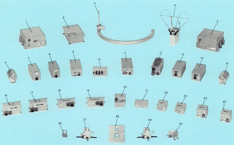 Project Mercury Capsule Communication Subsystem Equipment |
|
|
Design for the Future Providing space communication systems to meet the challenge of this space timetable is a task appropriate to Collins Radio, whose equipment transmitted America's first voice from space. |
|
| —Collins Signal, Issue 42, Volume 9-1, 1961 - Pages 8-13 | |